Transformers and Electrical Balance of Plant for BESS Sites
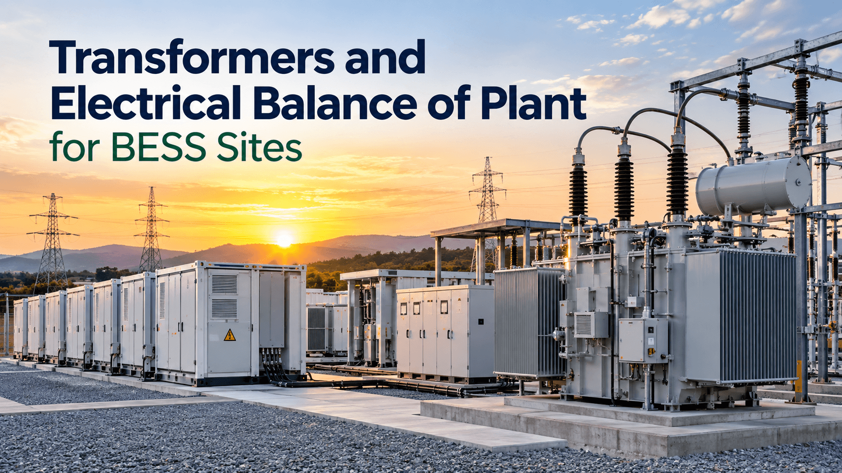
Battery energy storage system (BESS) projects are often discussed in terms of battery capacity, power conversion systems, and energy management software. But none of these components can deliver value without the electrical infrastructure that connects the battery system to the grid.
Transformers and the electrical balance of plant (eBoP) are central to that infrastructure. They manage voltage conversion, power distribution, protection, isolation, metering, and grid interconnection across the site.
For BESS developers and EPC teams, getting this part of the design right can have a direct impact on project cost, efficiency, safety, commissioning time, and long-term reliability.
What Is Electrical Balance of Plant in a BESS?
Electrical balance of plant refers to the electrical equipment and infrastructure required to connect the BESS to the grid and distribute power across the site.
The exact configuration varies by project size, voltage level, grid requirements, and site layout, but a typical BESS electrical balance of plant may include:
- Power transformers
- Medium-voltage switchgear
- Low-voltage distribution equipment
- Medium-voltage collectors
- Circuit breakers and disconnects
- Protection and control systems
- Auxiliary transformers
- Station service equipment
- AC cabling and busbars
- Revenue and operational metering
- Grounding and bonding systems
- Surge protection and lightning protection
- SCADA and communications interfaces
- Grid interconnection equipment
Together, these systems form the electrical pathway between the battery and the point of interconnection.
A well-designed eBoP should do more than move electricity. It needs to provide controlled, protected, measurable, and reliable power flow under normal operating conditions and during faults.
Why Transformers Matter in BESS Projects
Transformers are one of the most important components in the electrical architecture of a BESS site.
A battery system typically operates at a relatively low DC voltage. The power conversion system converts DC power into AC power, but the resulting AC voltage may still be too low for the site’s medium-voltage collection system or grid connection.
The transformer provides the required voltage conversion.
During charging, the electrical flow generally moves from the grid through the site’s electrical infrastructure, transformer, power conversion system, and into the battery.
During discharge, the direction reverses.
This means the transformer must be capable of handling the project’s operating profile in both directions.
Common Transformer Applications in BESS Sites
BESS projects can use several types of transformers depending on the system architecture.
Step-Up Transformers
Step-up transformers increase the AC voltage from the power conversion system to the medium-voltage level used by the site’s collector system.
For example, a PCS may produce AC power at a lower voltage, which is then stepped up to a medium-voltage level before power is distributed toward the substation and grid interconnection point.
The appropriate transformer ratio depends on the PCS output voltage, collector voltage, utility requirements, and overall site design.
Main Power Transformers
Larger BESS facilities may use a main power transformer at the substation to increase the site’s medium-voltage collection voltage to the transmission or distribution voltage required at the point of interconnection.
The main transformer can become a major project cost and schedule item, particularly when utility specifications, long manufacturing lead times, or high-voltage testing requirements are involved.
Early transformer selection is therefore important for project planning.
Auxiliary Transformers
BESS sites also require power for equipment that supports plant operation.
Auxiliary transformers can supply loads such as:
- HVAC systems
- Battery thermal management equipment
- Lighting
- Fire protection systems
- Control systems
- Communications equipment
- Security systems
- Battery management and monitoring equipment
These loads may appear small compared with the site’s export capacity, but they are essential to reliable operation.
How Transformers Affect BESS Efficiency
Transformer efficiency affects the amount of energy that ultimately reaches the grid or returns to the battery.
Every transformation introduces losses. These losses depend on factors such as transformer loading, winding resistance, core characteristics, cooling conditions, and operating temperature.
For a BESS that cycles frequently, even relatively small losses can accumulate over thousands of operating hours.
Transformer selection should therefore consider the project’s actual operating profile rather than simply selecting equipment based on maximum power.
A transformer that is appropriately sized for expected loading can help balance efficiency, cost, thermal performance, and future operating requirements.
Key Transformer Specifications for BESS Applications
Transformer selection should be coordinated with the PCS, switchgear, protection system, utility interconnection requirements, and site operating strategy.
Important considerations include:
Rated Power
The transformer must support the required continuous and short-duration power levels.
The design should account for charging and discharging conditions, expected overload requirements, ambient conditions, and potential future expansion.
Voltage Ratio
The primary and secondary voltages must match the requirements of the PCS, medium-voltage collector system, and grid interconnection architecture.
Impedance
Transformer impedance affects fault current, voltage regulation, and system performance.
It must be coordinated with the wider protection and electrical system design.
Cooling
Transformer cooling requirements depend on transformer rating, environmental conditions, installation arrangement, and expected loading.
Outdoor BESS projects may also face high ambient temperatures that affect transformer thermal performance.
Insulation and Environmental Conditions
The transformer specification should reflect the site’s environmental conditions, including temperature, altitude, humidity, pollution level, and exposure to weather.
Harmonic Performance
Power electronic equipment can introduce harmonic currents and voltages into an electrical system.
Transformer design should therefore be evaluated alongside PCS characteristics and the project’s power quality requirements.
Medium-Voltage Switchgear in BESS Electrical Infrastructure
Transformers are only one part of the electrical balance of plant.
Medium-voltage switchgear provides an important layer of control and protection between BESS equipment and the wider electrical network.
Depending on the site architecture, switchgear may provide:
- Circuit isolation
- Fault interruption
- Equipment protection
- Switching operations
- Bus sectionalization
- Transformer protection
- Collector circuit protection
- Maintenance isolation
Switchgear selection needs to account for the system voltage, fault level, continuous current, environmental conditions, protection philosophy, and applicable grid requirements.
For larger BESS projects, the collector system may contain multiple BESS blocks connected through medium-voltage feeders to a central substation.
Protection and Control for BESS Sites
Protection systems are critical because BESS sites combine batteries, power electronics, transformers, and grid-connected equipment.
A protection scheme should identify and isolate electrical faults while minimizing unnecessary interruption of healthy portions of the plant.
Depending on the architecture, protection may cover:
- Transformers
- Medium-voltage feeders
- Switchgear
- Busbars
- Substation equipment
- Ground faults
- Overcurrent conditions
- Differential faults
- Undervoltage and overvoltage
- Frequency deviations
- Reverse power conditions
Protection settings must be coordinated across the BESS, collector system, substation, and utility network.
Poor coordination can result in nuisance trips or, more seriously, delayed fault isolation.
BESS Grounding and Earthing
Grounding is another fundamental part of the electrical balance of plant.
A properly engineered grounding system helps manage fault currents and provides a controlled path for electrical faults. It also supports personnel safety and equipment protection.
BESS grounding design may need to address:
- Battery enclosures
- PCS equipment
- Transformers
- Switchgear
- Substation structures
- Cable screens
- Fences and gates
- Lightning protection systems
Grounding studies should be performed as part of the overall electrical design rather than treated as an isolated installation activity.
Metering and Grid Interconnection
Grid-connected BESS projects typically require accurate measurement of power flowing between the facility and the grid.
Metering may be used for:
- Revenue settlement
- Operational monitoring
- Performance verification
- Grid compliance
- Dispatch management
- Auxiliary consumption measurement
The metering architecture needs to align with utility and market requirements.
The location of metering equipment is also important because losses between the meter and the point of interconnection may affect how energy flows are measured and settled.
Cable and Collector System Design
The electrical balance of plant also includes the cabling and collection infrastructure connecting individual BESS blocks.
A typical architecture may look like:
Battery → PCS → Step-Up Transformer → MV Switchgear → MV Collector → Main Transformer → Grid
The physical layout can have a major impact on cable length, voltage drop, losses, installation costs, and maintenance access.
Longer cable runs can increase voltage drop and electrical losses. They can also increase material and installation costs.
For this reason, BESS block placement and substation location should be considered alongside the electrical design during early project development.
Designing eBoP Around the PCS
The PCS and transformer should not be selected independently.
The PCS determines important electrical characteristics that influence transformer and switchgear design, including:
- AC output voltage
- Rated active power
- Reactive power capability
- Power factor range
- Harmonic characteristics
- Fault current contribution
- Grid support functions
- Operating modes
The transformer, switchgear, protection system, and collector network must work within the electrical limits of the PCS.
Early coordination between the PCS supplier, transformer manufacturer, EPC contractor, and grid engineering team can reduce redesign and commissioning issues later in the project.
Grid Compliance Considerations
BESS facilities increasingly provide services beyond simple energy storage.
Depending on the market and interconnection requirements, a BESS may need to support functions such as:
- Reactive power control
- Voltage regulation
- Frequency response
- Active power control
- Ramp-rate control
- Low-voltage ride-through
- High-voltage ride-through
- Power factor control
These requirements influence the design of the electrical balance of plant.
For example, the transformer and switchgear must be capable of supporting the required operating envelope without creating unacceptable voltage or thermal conditions.
Grid studies should therefore be performed early enough to influence equipment selection.
Thermal Design and Environmental Conditions
BESS equipment operates outdoors on many utility-scale projects, which makes environmental conditions an important design consideration.
High ambient temperatures can affect transformer loading, cable ampacity, switchgear ratings, and PCS performance.
Other factors may include:
- Altitude
- Humidity
- Dust
- Salt exposure
- Corrosive environments
- Rainfall
- Solar radiation
Equipment specifications should reflect actual site conditions rather than relying solely on standard ratings.
This is especially important for projects in hot or harsh climates, where thermal derating can affect available power.
Common BESS eBoP Design Challenges
Several issues repeatedly appear during BESS electrical design and project execution.
Equipment Mismatch
Selecting the PCS, transformer, and switchgear separately can create mismatches in voltage, current, impedance, protection, or operating range.
A coordinated electrical design helps avoid these problems.
Undersized Auxiliary Systems
Auxiliary loads are sometimes treated as an afterthought.
However, HVAC, controls, fire protection, communications, and other auxiliary systems can consume significant energy and are necessary for plant availability.
Inadequate Fault Studies
Short-circuit and protection studies should reflect the actual equipment configuration.
Changes to transformer impedance, PCS technology, or collector topology can affect fault levels and protection settings.
Late Utility Requirements
Grid operators may impose detailed requirements for protection, metering, communications, power quality, and control.
Identifying these requirements early reduces the risk of costly design changes.
Long-Lead Equipment
Large transformers and specialized switchgear can have long procurement timelines.
Waiting until late-stage design to finalize these components can become a major project schedule risk.
How to Optimize Electrical Balance of Plant Costs
The lowest equipment purchase price does not necessarily produce the lowest project cost.
BESS developers should evaluate total installed and lifecycle costs.
Important factors include:
- Equipment cost
- Transportation
- Civil works
- Installation
- Cable quantities
- Transformer losses
- Auxiliary consumption
- Maintenance
- Replacement requirements
- Commissioning
- Downtime risk
Site layout can also make a significant difference.
Optimizing the distance between BESS blocks, transformers, switchgear, and the substation can reduce cable quantities and electrical losses while simplifying construction.
A Practical Approach to BESS eBoP Design
A structured design process can help reduce integration risks.
1. Define the Grid Connection Requirements
Start with the point of interconnection, grid voltage, export and import limits, protection requirements, and applicable grid code.
2. Establish the BESS Electrical Architecture
Define the battery block, PCS, transformer, medium-voltage collection system, substation, and grid connection arrangement.
3. Complete Electrical Studies
Typical studies can include:
- Load flow
- Short circuit
- Protection coordination
- Harmonic analysis
- Voltage stability
- Grounding
- Arc flash, where applicable
- Transient or dynamic studies where required
4. Select Major Electrical Equipment
Use the study results to finalize transformer, switchgear, cable, protection, and metering specifications.
5. Coordinate Protection and Controls
Ensure protection settings, PCS controls, transformer characteristics, and utility requirements work together.
6. Validate the Complete System
Factory testing, site testing, commissioning, and grid compliance testing should verify the complete electrical chain rather than individual components alone.
What BESS Developers Should Ask Transformer and eBoP Suppliers
Before selecting an electrical equipment supplier, project teams should ask practical questions about the complete system.
For transformers:
- What is the rated power and voltage range?
- What is the transformer impedance?
- How are thermal limits calculated?
- What cooling method is used?
- How does the design handle the expected BESS duty cycle?
- What harmonic considerations have been evaluated?
- What testing is included?
- What is the expected manufacturing lead time?
For the wider eBoP:
- How is the PCS integrated with the MV system?
- What protection philosophy is proposed?
- How are auxiliary loads supplied?
- Where is revenue metering located?
- How are grounding and lightning protection handled?
- What electrical studies are included?
- How are grid compliance requirements addressed?
- Which equipment is included in the supplier’s scope and which remains with the EPC?
Clear scope boundaries are particularly important in BESS projects because responsibilities can otherwise fall between the PCS supplier, transformer supplier, EPC, and utility.
The Role of eBoP in BESS Project Performance
Battery capacity and PCS power ratings are highly visible when evaluating a BESS project, but the electrical balance of plant determines how effectively that equipment connects to the grid.
Transformers provide the critical voltage conversion between the PCS, collection network, and grid. Switchgear, protection, cabling, grounding, metering, controls, and auxiliary systems complete the electrical infrastructure required for safe and reliable operation.
The best eBoP design is not simply the one with the lowest upfront equipment cost. It is the design that balances capital cost, electrical efficiency, reliability, safety, maintainability, grid compliance, and future operating requirements.
For developers and EPC teams, involving the eBoP and transformer design early in the project can reduce integration risk and prevent expensive changes later.
Key Takeaways
Transformers and electrical balance of plant are fundamental to the performance of utility-scale BESS projects.
The most important considerations are:
- Match transformer ratings and voltage ratios to the PCS and grid architecture.
- Design the MV collection system around the actual BESS configuration.
- Coordinate protection across the BESS, substation, and utility network.
- Account for transformer and electrical losses over the project’s operating life.
- Consider environmental and thermal conditions during equipment selection.
- Complete electrical studies before finalizing major equipment.
- Define equipment and integration responsibilities clearly between suppliers and EPC teams.
- Consider long-lead electrical equipment early in the project schedule.
- Evaluate eBoP using lifecycle cost and reliability, not only initial purchase price.
A BESS can only perform as well as the electrical infrastructure connecting it to the grid. Getting transformers and eBoP right from the beginning creates a stronger foundation for efficient, reliable, and grid-compliant energy storage projects.
Frequently Asked Questions
What is electrical balance of plant in a BESS?
Electrical balance of plant includes the electrical equipment and infrastructure required to connect a BESS to the grid. This can include transformers, switchgear, cables, protection systems, metering, grounding, auxiliary power, and control systems.
What type of transformer is used in a BESS?
BESS projects can use step-up transformers between the PCS and medium-voltage collection system, main power transformers at the substation, and auxiliary transformers for plant loads. The required configuration depends on the project’s electrical architecture.
Why does a BESS need a transformer?
A transformer changes AC voltage between different parts of the electrical system. In many BESS projects, it increases the PCS output voltage to the medium-voltage level used for collection and grid interconnection.
What equipment is included in BESS eBoP?
Typical equipment includes transformers, MV switchgear, circuit breakers, cables, protection and control systems, metering, grounding, auxiliary power systems, and communications infrastructure.
How does transformer selection affect BESS performance?
Transformer efficiency, impedance, thermal capacity, voltage ratio, and cooling characteristics can affect electrical losses, voltage regulation, fault levels, operating limits, and overall BESS performance.
What electrical studies are required for a BESS project?
Depending on the project, studies may include load flow, short circuit, protection coordination, grounding, harmonic analysis, voltage stability, arc flash, and dynamic or transient studies required by the grid operator.
Why is early eBoP planning important?
Early planning allows the project team to coordinate the PCS, transformers, switchgear, cables, protection systems, grid requirements, and site layout. This can reduce redesign, procurement delays, integration problems, and commissioning risks.