

LFP Battery Pack: Design, Assembly and Manufacturing
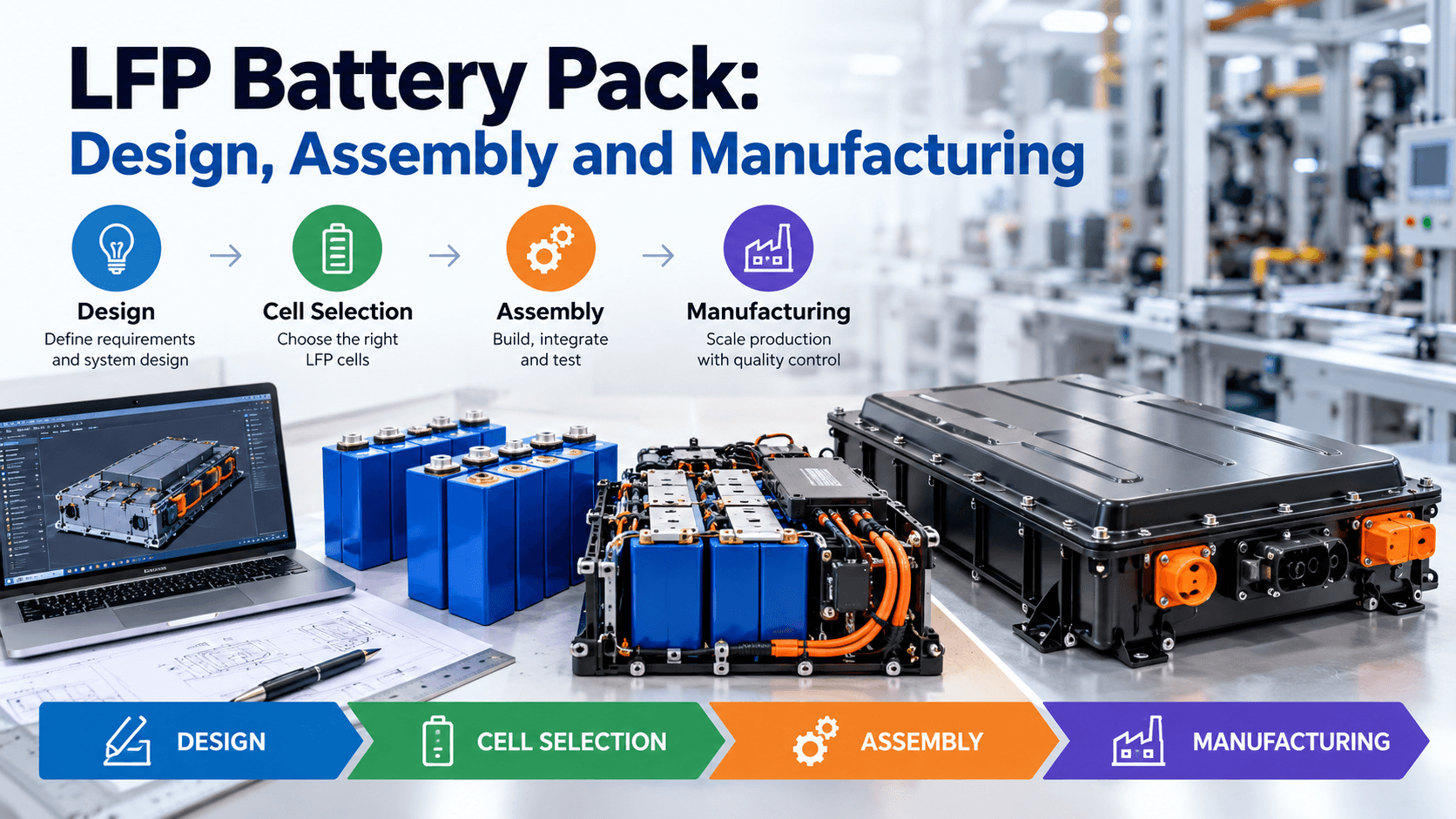
What Is an LFP Battery Pack?
An LFP (lithium iron phosphate) battery pack is a rechargeable energy storage system built from lithium iron phosphate cells connected in series and parallel to deliver a specific voltage, capacity, and power output.
LFP chemistry is widely used in electric vehicles, energy storage systems, industrial equipment, backup power, and other applications where safety, long cycle life, and stable performance matter.
A complete battery pack typically includes:
- LFP battery cells
- Busbars or interconnects
- Battery Management System (BMS)
- Cell monitoring and balancing circuits
- Fuses and contactors
- Thermal management components
- Enclosure and mechanical supports
- Wiring harnesses and connectors
- Charging and communication interfaces
The cells provide the stored energy, but the rest of the pack determines how safely and reliably that energy can be delivered.
Why Use LFP Battery Chemistry?
LFP batteries have several characteristics that make them attractive for demanding applications.
Long Cycle Life
LFP cells can support a high number of charge and discharge cycles when operated within appropriate voltage, temperature, and current limits.
This makes them particularly useful for applications where the battery is charged and discharged frequently.
Thermal and Chemical Stability
Lithium iron phosphate chemistry is generally more thermally stable than several other lithium-ion chemistries. That does not make an LFP battery inherently risk-free, however. Proper electrical protection, thermal design, mechanical construction, and manufacturing controls are still essential.
Good Safety Characteristics
A well-designed LFP pack combines the chemistry’s stability with safeguards such as overcurrent protection, cell voltage monitoring, temperature sensing, and controlled charging.
Suitable for High-Use Applications
LFP packs are commonly considered for applications such as:
- Electric mobility
- Solar energy storage
- Commercial and industrial energy storage
- Material-handling equipment
- Telecom backup systems
- Portable power systems
LFP Battery Pack Design
Battery pack design starts with the application’s electrical, mechanical, environmental, and safety requirements.
Before selecting cells, engineers normally define parameters such as:
- Nominal system voltage
- Required energy capacity
- Continuous power
- Peak power
- Charge and discharge current
- Operating temperature
- Available physical space
- Target weight
- Expected cycle life
- Communication requirements
- Protection requirements
The goal is not simply to maximize battery capacity. The pack needs to deliver the required performance within defined safety and operating limits.
Choosing the Right LFP Cells
Cell selection is one of the most important decisions in battery pack design.
Common LFP cell formats include cylindrical, prismatic, and pouch cells. Each has different mechanical, thermal, electrical, and manufacturing considerations.
Important cell specifications include:
- Nominal voltage
- Rated capacity
- Maximum continuous current
- Peak current capability
- Recommended charging limits
- Operating temperature range
- Internal resistance
- Cycle-life characteristics
- Physical dimensions
- Manufacturer quality and traceability
Cells should be selected based on the actual duty cycle rather than capacity alone.
For example, a battery designed for a high-power application may require cells with strong continuous-current performance, while a stationary storage system may place greater emphasis on energy capacity and cycle life.
Series and Parallel Configuration
LFP cells are connected in series to increase voltage and in parallel to increase capacity and current capability.
A battery configuration is often described as NsNp.
For example, a 16S configuration contains 16 cells or cell groups connected in series. With suitable cells, this can produce a nominal pack voltage in the range commonly used for 48 V-class systems.
If multiple cells or cell groups are connected in parallel, the available capacity increases.
The basic relationships are:
Pack nominal voltage ≈ number of series cells × cell nominal voltage
Pack capacity ≈ number of parallel cells × cell capacity
Actual pack specifications also depend on cell characteristics, BMS limits, temperature, operating conditions, and the application’s allowable voltage window.
Battery Management System
The Battery Management System, or BMS, is a critical part of an LFP battery pack.
It monitors the battery and controls or coordinates protection functions based on parameters such as:
- Individual cell voltage
- Pack voltage
- Charge and discharge current
- Cell and pack temperature
- State of charge
- Fault conditions
- Cell imbalance
Depending on the application, a BMS may also provide passive or active cell balancing, communication through interfaces such as CAN or RS-485, data logging, diagnostics, and contactor control.
A good BMS design should be matched to the cell chemistry, number of series cells, current requirements, operating environment, and system architecture.
Thermal Management
LFP cells generally have favorable thermal characteristics, but battery packs still generate heat during charging and discharging.
Thermal design becomes increasingly important as pack power and energy density increase.
Depending on the application, thermal management may use:
- Natural convection
- Forced-air cooling
- Thermal interface materials
- Heat sinks
- Liquid cooling
- Heating systems for cold environments
The objective is to keep cells within their specified operating temperature range and minimize temperature differences between cells.
Uneven temperatures can contribute to differences in cell behavior and may affect pack performance and aging.
Mechanical Design of the Pack
The enclosure must protect cells and electrical components from mechanical, environmental, and operational stresses.
Mechanical design typically addresses:
- Cell restraint
- Vibration
- Shock
- Expansion and contraction
- Moisture and dust protection
- Cable routing
- Service access
- Connector placement
- Impact protection
- Electrical isolation
Prismatic and pouch cells require particular attention to mechanical compression and swelling behavior. The appropriate approach depends on the cell manufacturer’s specifications.
LFP Battery Pack Assembly Process
The exact assembly process varies by cell format and application, but a typical production workflow looks like this.
1. Incoming Cell Inspection
Cells are inspected before assembly.
Typical checks can include:
- Visual inspection
- Dimensions
- Open-circuit voltage
- Internal resistance
- Capacity data
- Manufacturing lot information
- Physical damage
Traceability is important because battery performance depends heavily on cell consistency.
2. Cell Matching and Grading
Cells intended for the same pack should have compatible electrical characteristics.
Manufacturers may grade cells according to capacity, resistance, voltage behavior, and other parameters.
The goal is to reduce variation between cells and improve pack consistency.
3. Cell Arrangement
Cells are positioned according to the pack’s series-parallel architecture.
Insulating materials and mechanical supports are installed as required.
The design must prevent unintended contact between conductive components and the enclosure or neighboring cells.
4. Electrical Interconnection
Cells are connected using appropriate busbars, connectors, or other interconnect methods.
The selected joining method depends on the cell format and manufacturing design.
Production processes need to control connection quality, resistance, alignment, and mechanical integrity.
5. BMS Installation
The BMS and its associated wiring are installed and connected to the cell groups.
Voltage-sensing connections need to be correctly sequenced and securely connected. Incorrect wiring can damage electronics or create a hazardous condition.
Temperature sensors are positioned at appropriate locations to monitor the battery effectively.
6. Protection Components
Depending on the pack architecture, protection hardware can include:
- Fuses
- Contactors
- Pre-charge circuits
- Current sensors
- Service disconnects
- High-voltage interlocks
These components help isolate the battery during faults and control how electrical power flows through the system.
7. Enclosure Assembly
After electrical and mechanical checks, the battery assembly is installed into its enclosure.
The final assembly should provide appropriate protection while maintaining required cooling, insulation, sealing, and serviceability.
8. End-of-Line Testing
Every finished pack should undergo appropriate electrical and functional testing before shipment.
Testing may include:
- Voltage verification
- Insulation testing
- BMS communication testing
- Cell-voltage verification
- Temperature-sensor checks
- Charge and discharge testing
- Protection-function verification
- Leak or ingress testing where applicable
- Functional safety checks
LFP Battery Pack Manufacturing Quality Control
Quality control needs to cover the entire production process, not just final testing.
Important controls include incoming inspection, controlled assembly processes, traceability, calibrated test equipment, and documented acceptance criteria.
A manufacturing quality system should be capable of identifying issues such as:
- Damaged cells
- Incorrect cell orientation
- Poor electrical connections
- Incorrect BMS wiring
- Insulation failures
- Loose mechanical components
- Sensor installation errors
- Incorrect firmware or configuration
- Inadequate sealing
For larger-scale production, automated inspection and production data collection can improve consistency and traceability.
Battery Pack Safety Considerations
Battery pack safety should be designed into the system from the beginning rather than added during final assembly.
Key areas include electrical protection, thermal management, mechanical protection, cell monitoring, fault detection, and safe charging.
Depending on the market and application, manufacturers may also need to consider applicable battery and transportation standards and certification requirements.
The specific requirements vary by product type, operating voltage, geography, transportation method, and intended use. Engineering and compliance teams should identify the applicable standards before finalizing the design.
LFP Battery Pack Manufacturing Challenges
Manufacturing battery packs at scale introduces challenges beyond assembling cells.
Cell-to-Cell Variation
Even cells from the same production batch can vary in capacity and resistance. Controlling this variation is important for pack consistency.
Thermal Uniformity
Large packs can develop temperature gradients. The thermal system needs to account for the physical arrangement of cells and expected operating conditions.
BMS Integration
Electrical, firmware, and mechanical integration can become complex as the number of cells and system features increases.
Production Traceability
Manufacturers need to know which cells, components, firmware versions, and test results were associated with each finished battery pack.
Scaling Production
A process that works for a small prototype may not provide sufficient consistency or throughput for commercial manufacturing.
Production tooling, test automation, process controls, and quality systems become increasingly important as volumes increase.
From Prototype to Mass Production
A successful LFP battery pack usually passes through several development stages.
Concept design: Define application requirements and preliminary electrical architecture.
Engineering prototype: Validate cell configuration, BMS, mechanical design, thermal behavior, and electrical performance.
Design validation: Test the pack under expected operating and environmental conditions.
Manufacturing validation: Confirm that the production process can repeatedly build packs to specification.
Pilot production: Produce a controlled batch and identify process problems before volume production.
Mass production: Implement standardized processes, quality controls, traceability, and continuous improvement.
This progression helps separate design problems from manufacturing problems before large-scale production begins.
Key Factors in LFP Battery Pack Design
A reliable LFP battery pack is the result of several systems working together.
The cells determine much of the available energy and power. The BMS manages electrical behavior and protection. Thermal management controls operating temperature. Mechanical design protects the cells and components. Manufacturing processes determine whether the final packs consistently meet the design requirements.
For that reason, battery pack development should be treated as a system engineering problem rather than simply a cell assembly exercise.
Frequently Asked Questions
How many LFP cells are needed for a battery pack?
It depends on the required voltage and capacity. Cells are connected in series to increase voltage and in parallel to increase capacity. The required configuration is determined by the application’s electrical requirements.
Is an LFP battery pack safer than other lithium-ion batteries?
LFP chemistry has favorable thermal and chemical stability characteristics, but safety depends on the complete battery system. Cell quality, BMS design, electrical protection, thermal management, mechanical construction, and manufacturing quality all matter.
What does a BMS do in an LFP battery?
A BMS monitors cell voltage, temperature, current, and other operating parameters. Depending on the design, it can also balance cells, communicate with external systems, and control protective devices.
Can LFP batteries be used in electric vehicles?
Yes. LFP batteries are used in various electric mobility applications. Their suitability depends on the vehicle’s required energy, power, weight, charging behavior, operating temperature, cost, and packaging requirements.
What is the most important part of LFP battery manufacturing?
There is no single component that determines quality. Consistent cell quality, correct electrical assembly, reliable BMS integration, thermal and mechanical design, process control, and comprehensive testing all contribute to a reliable finished pack.