



Introduction
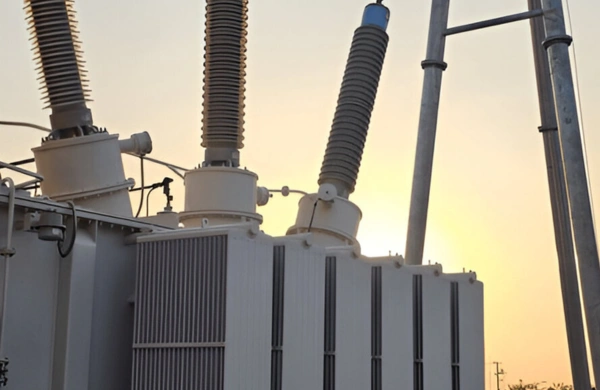
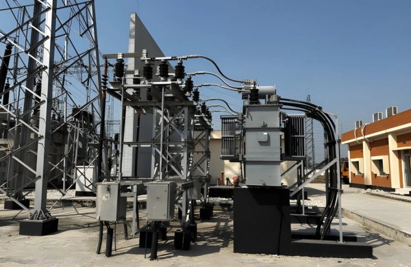
Industrial processes that rely on direct current (DC)—such as electrolysis, steelmaking, mining, and variable-speed motor drives—depend heavily on rectifier transformers. These specialized transformers convert alternating current (AC) from the grid into a controlled, rectified DC output, ensuring continuous, stable operation of critical systems.
While standard transformers merely adjust voltage levels, rectifier transformers must handle high harmonic loads, non-linear currents, and continuous operation under demanding thermal conditions. They are engineered for ruggedness, efficiency, and precise voltage control—making them indispensable in industries that operate around the clock.
In this article, we’ll explore the working principles, design architecture, and key performance parameters of rectifier transformers, and the standards that govern reliable performance in continuous-duty industrial environments.
Know About How Rectifier Transformers Support Continuous Operations
Zetwerk provides high-quality Precision Components and all secondary operations.
Submit the relevant part drawings, 3D files, and other information by clicking on the button below.

1. Understanding Rectifier Transformers
A rectifier transformer is a specialized power transformer that supplies AC power to a rectifier circuit (typically diode or thyristor-based), which converts it into DC.
Unlike standard distribution transformers, rectifier transformers must manage:
- Non-linear load currents generated by the rectifier circuit.
- High harmonic distortion that can affect transformer insulation and system stability.
- Continuous high-current operation in harsh industrial environments.
To accommodate these demands, rectifier transformers are designed with reinforced insulation, increased thermal capacity, and customized vector group configurations that support harmonic suppression and DC voltage control.
2. Working Principle and Configuration
Rectifier transformers work in conjunction with power electronic rectifier units. The AC supply from the grid is stepped down (or sometimes up) to the required level and then fed into a rectifier bridge, which converts it into DC.
Basic Operation Steps:
- AC Input: Transformer receives AC voltage from the supply.
- Voltage Conversion: The winding ratio determines the secondary voltage required by the rectifier.
- Rectification: Diodes or thyristors convert the AC to DC.
- Filtering: Capacitors and reactors smooth the output for steady DC supply.
Common Rectifier Configurations:
- 6-Pulse Rectifier: Basic design for small to medium applications.
- 12-Pulse Rectifier: Reduces harmonics and improves DC quality.
- 24-Pulse Rectifier: Used for large-scale DC systems like electrolysis and DC drives.
Multi-winding units with interphase transformers are commonly used for harmonic mitigation in higher-pulse configurations.
3. Construction and Design Characteristics
Rectifier transformers differ from conventional power transformers in design, construction, and materials due to the unique electrical and thermal stresses they experience.
a. Core Design
Built from Cold Rolled Grain Oriented (CRGO) or amorphous steel laminations, optimized for low core losses. Core geometry and flux density are carefully designed to minimize harmonic saturation.
b. Windings
- Primary Windings: Designed for grid voltage, usually delta-connected.
- Secondary Windings: Often star or zigzag connected, with multiple secondary windings feeding rectifier bridges.
Copper or aluminum conductors with high-temperature insulation (Class F/H) are used.
c. Cooling Systems
Depending on size and duty cycle:
- ONAN (Oil Natural Air Natural) for smaller units.
- ONAF / OFWF (forced oil or water cooling) for high-capacity, continuous-duty applications.
d. Insulation and Mechanical Design
Enhanced insulation withstands DC bias and harmonic stress. Coil clamping structures are reinforced to handle electromagnetic forces under short-circuit conditions, typically achieved through precision winding, vacuum pressure impregnation (VPI), and robust mechanical clamping.
4. Electrical and Thermal Performance Parameters
| Parameter | Typical Value / Range | Significance |
| Voltage Rating | Up to 35 kV (primary) | Defines grid connection compatibility |
| DC Output Voltage | 12 V – 1,000 V DC | Varies with process requirement |
| Output Current | 100 A – 50,000 A | High currents for electrolysis or plating |
| Efficiency | 96–98% | High conversion efficiency for continuous operation |
| Cooling Method | ONAN / ONAF / OFWF | Determines thermal performance |
| Insulation Class | F or H | Ensures temperature stability under 24/7 load |
Performance is validated through heat-run, impulse, and harmonic distortion tests to ensure reliable operation in process-critical industries.
5. Industrial Applications of Rectifier Transformers
a. Metallurgy and Electrolysis Plants
Used in aluminum, copper, and zinc electrolysis for continuous DC power supply. Their ability to handle high current and low ripple ensures steady metal deposition and efficiency.
b. Chemical and Electroplating Industries
Support continuous DC power for processes like electroplating, anodizing, and chlorine production.
c. Steel Manufacturing (Arc and Ladle Furnaces)
Power rectifier systems for electric arc furnaces (EAF) and ladle refining furnaces (LRF), enabling controlled arc characteristics and temperature stability.
d. DC Drives and Rolling Mills
Provide controlled DC voltage for large DC motors in rolling mills, conveyor systems, and cranes.
e. Mining and Smelting Applications
Supply stable DC to electro-winning and smelting operations running non-stop in harsh conditions.
f. Renewable Energy and HVDC Links
Support inverter-based renewable systems and high-voltage DC transmission, providing isolation and controlled rectification.
6. Quality Assurance and Testing Standards
To ensure reliability in 24/7 operation, rectifier transformers undergo rigorous testing to meet global standards.
Standards Followed:
- IEC 61378-1 / 2: Power transformers for rectifier and converter duty.
- IEEE C57.18: Guide for converter transformers.
- ANSI C57 Series: Performance and testing standards.
- NEMA TR1: Transformer efficiency and safety.
Testing Procedures Include:
- No-Load and Load Loss Tests
- Short-Circuit Withstand Tests
- Temperature Rise and Heat Run Tests
- Impulse Voltage Tests
- Harmonic Distortion and Acoustic Noise Measurement
Manufacturers typically use automated test benches and data logging systems to ensure traceability and consistency in every unit produced.
7. Categories of Rectifier Transformer Manufacturers
Rectifier transformer manufacturers generally fall into a few distinct categories, depending on the industries and duty cycles they serve:
1. The Large-Scale HVDC & Metal-Refining Specialist
Manufacturers in this category produce large rectifier transformers for metal refining and HVDC transmission systems, typically at the highest voltage and current ranges.
2. The Converter-Transformer Specialist
This category focuses on converter transformers with advanced harmonic reduction and digital monitoring, often serving renewable energy and industrial power conversion applications.
3. The Dry-Type Rectifier Specialist
Manufacturers here specialize in dry-type rectifier transformers for industrial and offshore applications where oil-filled designs aren’t practical.
4. The Custom Industrial-Power Specialist
This category offers custom rectifier and converter transformers built to order for specific industrial power system requirements.
8. Technological Advancements in Rectifier Transformer Design
The next generation of rectifier transformers incorporates smarter, more efficient, and more durable design features:
- Amorphous Core Technology: Reduces no-load losses by up to 70%.
- Digital Condition Monitoring: Sensors track temperature, load, and harmonics in real time.
- Hybrid Cooling Systems: Combine oil and water cooling for superior heat management.
- High-Frequency Converter Integration: Enables smoother DC output for precision control.
- Eco-Friendly Materials: Use of biodegradable oils and recyclable steel laminations.
These advancements balance energy efficiency, operational reliability, and long service life for demanding applications, and are shaping design priorities across the industry.
Conclusion
Rectifier transformers are the backbone of industries that depend on continuous DC power for production and process efficiency. Their ability to withstand non-linear loads, suppress harmonics, and operate continuously under high thermal and electrical stress makes them indispensable to modern heavy industry.
As industrial automation and renewable integration continue to grow, demand for robust, efficient, and standards-compliant rectifier transformers will only increase—supporting the metallurgical, chemical, and renewable energy sectors with reliable, high-duty power infrastructure.
Explore Zetwerk’s transformer manufacturing capabilities →
FAQs
a. It supplies AC power to rectifiers that convert it to DC for processes like electrolysis, plating, and DC drives.
a. It’s designed for continuous DC load, harmonic suppression, and multi-winding configurations.
a. Metallurgy, chemicals, electroplating, mining, and renewable energy systems.
a. IEC 61378, IEEE C57.18, ANSI C57 series, and NEMA TR1 are the primary global standards.
a. ONAN for smaller units, and ONAF or OFWF (forced oil or water cooling) for high-capacity, continuous-duty applications.
